 |
UK Broadcast Transmission |
|
|||||||||||
THE TRANSMISSION GALLERY
BELMONT
| Photos by Mark G7RJV | Page last updated: 2013-04-28 |
| Belmont in Lincolnshire Visited the site on a nice sunny day, which was a vast improvement on the last time I visited this site in 2010. Then there was a light mist and started to rain shortly after visiting. Sun worked against me for some pictures, but using a telephoto lens I was able take pictures from three different locations around the site. Pictures provided are taken from the full set. Belmont is not a easy site to take pictures of due to the height of the mast and distance between the local lanes and the mast make taking detailed pictures very difficult without using a very long telephoto lens. Not certain what the future is for the three sets of UHF antenna below the main S1 and S2 antenna which are still in position and left over from DTT and Channel 5 analogue days. The future they could be used for local TV or other services which will eventually share the UHF band or removed when possible. Heights of various antenna are taken from Ofcom TxParams datasheet. |


| UHF S1 Antenna |
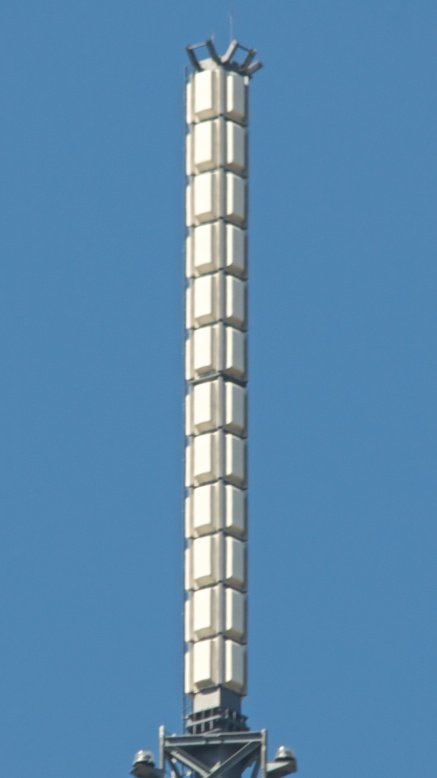
| UHF S1 antenna. |

| UHF S2 Antenna |
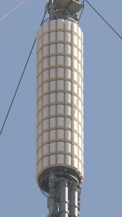
| UHF S2 antenna. |

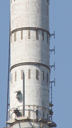
| The purpose of the tubes below the S2 antenna was not obvious as they are located on one side of the mast and on the other two sides of the mast have wire mesh panels. The thinking at the time was this was to make space around that part of the mast available by passing the UHF feeders through the tubes. TCPD comments: I would be reasonably confident in saying that these are present for structural reasons and are not antennas. I believe that after the Emley Moor failure, the design of the structures was reviewed and two significant additions were made at Belmont and Winter Hill. Firstly, as the strength of the leg joints in tension was considered to be inadequate, the "leg clamps" were added. These can be seen in the photos throughout the lattice section of the mast. Substantial castings were clamped to the legs on either side of the joints and tied together by steel bars. This relieves the flanged joint in the legs from taking tensile loads. In a static situation the leg joints are in compression but when bending loads are included the load could be tensile. Secondly sets of "chain dampers" were added. Basically large chains (tons?) hanging inside steel tubes. In the event that the mast oscillates, the chains will bang about and absorb some of the energy. This is probably what is below the S2 antenna. |

| Further comments about the tubes containing chain dampers: When I looked at the pictures of the other cylindrical masts these tubes cannot be seen, unless they are hidden inside the masts. I have seen the chains hanging down from the stay wires at Winter Hill, but Belmont does not have these. Also why are these damping tubes on one side of the mast and not on all sides to balance out the load, unless loading is not a problem. Was there reason why Crown Castle/NTL did not replace these masts with a lattice structure, would have been more practical and probably stronger? TCPD replies: The masts were originally completely clad in GRP weathershields, so wind loading was certainly not an issue then, and I would not think the imbalance is significant now, no more than having a big dish out on one side. And that's why the dampers were not to be seen as well. I have heard of oscillations on stays ("Galloping" stays) occurring at a number of sites over the years and I assume that was a problem at Black Hill (and Winter Hill?) and resulted in the chains being added. More commonly the solution was to retension the stays. I don't think it is as dangerous for the mast as the serious oscillations in the cylindrical masts themselves, but it is undesirable of course because as well as shaking everything, it quickly wears out the links and pins attaching the wires to the mast. Belmont and Winter Hill were owned by IBA/NTL so they must have been content that the modifications made them safe in the long term so there was no justification for the huge cost of replacing them. The BBC's cylindrical structures didn't have the same problems. |

| BBC VHF band II antenna and BBC DAB antenna at 291m at the top of this picture. Below a former UHF antenna |


| Former Channel 5 antenna. |


| Three sets of antenna. |
| Yorkshire DAB - 232m |

| Yorkshire DAB - 232m |


| Former Mux A and Mux B UHF antenna located around 229m. |

| ILR VHF antenna located at 222m, also used by Classic FM rather than the main national radio antenna located at 291m. This unusual arrangement was a result of a cost dispute with the BBC concerning combiner sharing fees. The BBC regarded themselves as one user and Classic FM the other, so proposed a 50-50 fee structure. At most sites it was still regarded as cost effective to accept this arrangement, however at Belmont and Blaenplwyf it was deemed cheaper to erect a separate antenna (originally a Sira mixed polarisation antenna (75% vertical, 25% horizontal) at 17kW ERP). We understand that the dispute was later resolved after legal action, and sharing fees adjusted to a per-service basis. |


| At the top of this picture are mast mounted dipoles which, using BBC mast outline drawings from the 1980s, show H and V mast mounted dipoles for band II located at 198m and below a mast platform at 207m. These in the drawing are for BBC Radio Lincolnshire. At this point Ofcom TxParams go astray, as they say Classic FM and ILR service antenna is located at 222m, which would put the antenna above the mast platform. Making use of the two tier antenna shown in the pictures above and Radio Lincolnshire as being 229m, this would put that antenna around the UHF skew fire panels above the VHF antenna. Therefore it is possible that Ofcom TxParams datasheet is wrong here and that BBC Radio Lincolnshire is still using these antenna which are located at 198m AGL and not 229m as shown in Ofcom TxParams. |

| Former Mux C and D antenna at 189m. |

| Upper UHF Rx panel on Emley Moor. |


| Lower UHF panel on Emley Moor. Band II antenna on Holme Moss |
UHF Transmitting aerial for the Belmont Transmitting Station
| |
Back to TX Gallery index | TX main index
|