 |
UK Broadcast Transmission |
|
|||||||||||
THE TRANSMISSION GALLERY
LLANDRINDOD WELLS
| Photos by TCPD | Page last updated: 2012-06-26 |
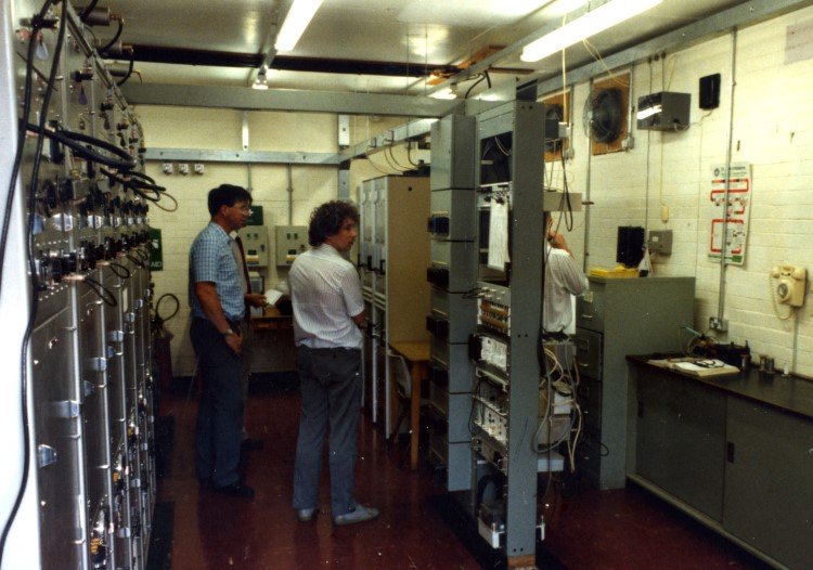
| Llandrindod Wells before FM re-engineering was probably very little changed from when it was installed in the 1960s. |
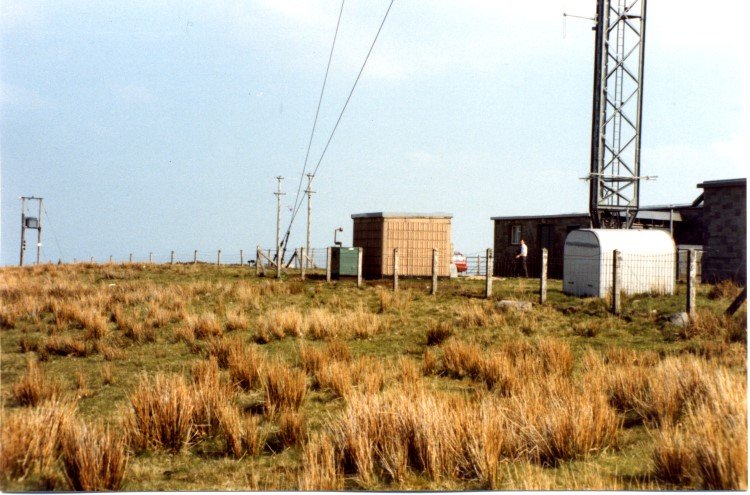
| Outside a peaceful, if somewhat bleak and windswept mountain top. Two wooden poles carry receiving antennas. |
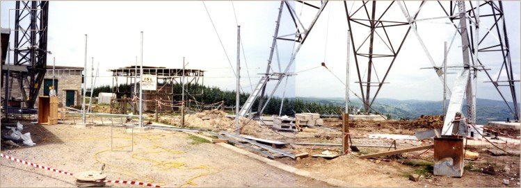
| Until they came to build a new tower. |
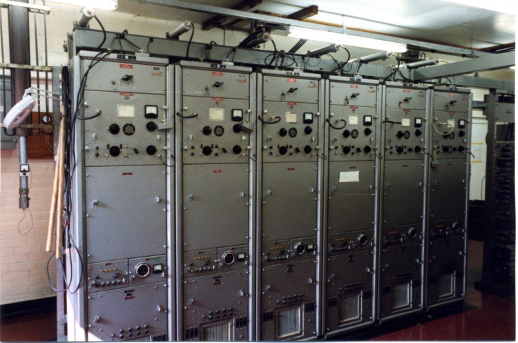
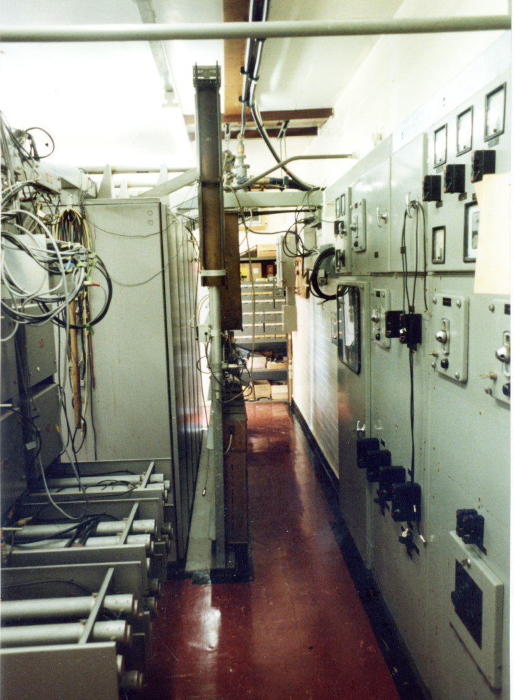
| Inside are the amplifiers for Home, Light and Third programmes. Note the window which allows you to see the valves inside, and forms part of the monitoring system as follows: (Cathode glowing) AND (Anode not glowing) AND (Meter reading) = GOOD (Cathode not glowing) OR (Anode glowing) OR (no meter reading) = BAD |
| Main and reserve "translators" for each programme. |
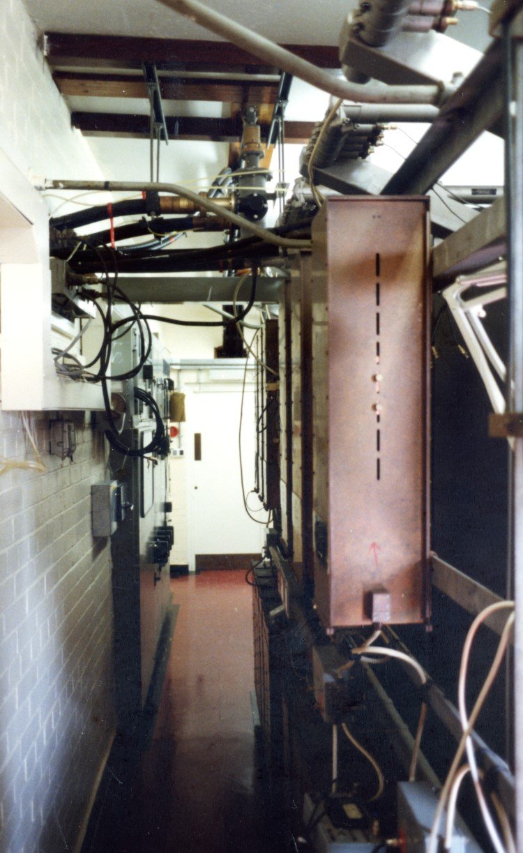
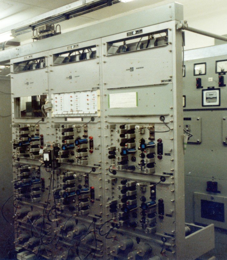
| Behind the amplifiers are the channel combining filters using copper boxes as the resonators. |
| Behind the translators the size of the input splitting filter resonators is apparent. A later development was the "Helical Resonator" to do the same job in low power combiners and splitters. It was about 3" diameter but only 6" long. |
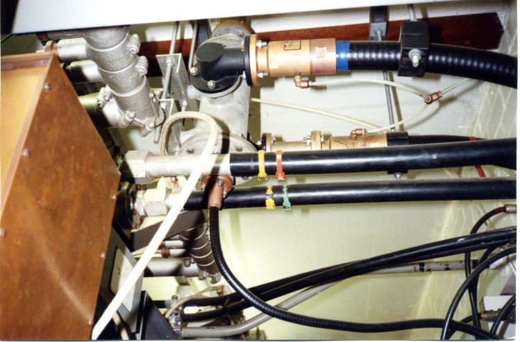
| Main feeders to the FM antenna used cable with solid aluminium tube outer conductor, pre-dating the general use of corrugated cables like the Andrews HJ7 air spaced cable seen on the UHF feeders. |
| |
Back to TX Gallery index | TX main index
|