 |
UK Broadcast Transmission |
|
|||||||||||
THE TRANSMISSION GALLERY
MOORSIDE EDGE
| Photos by MarksPictures | Page last updated: 2023-02-01 |
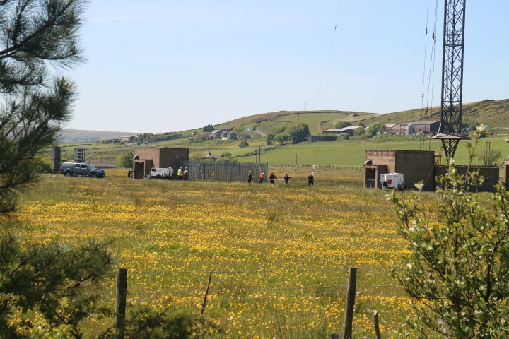
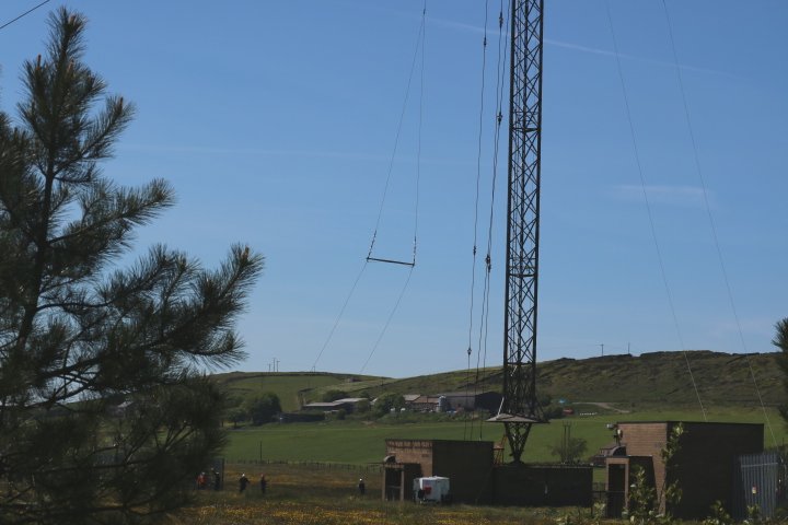
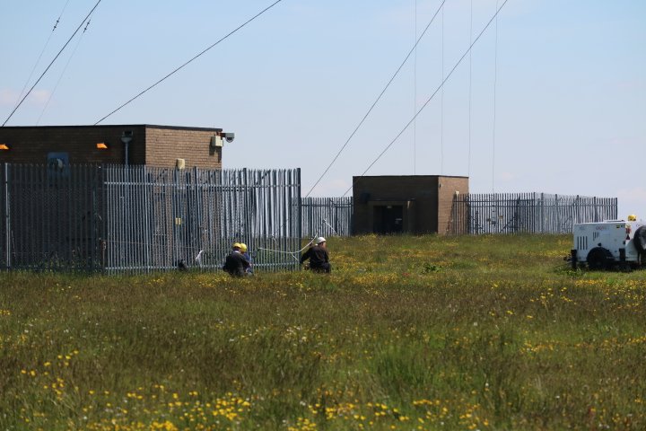
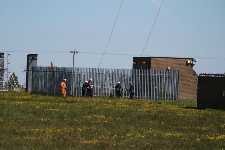
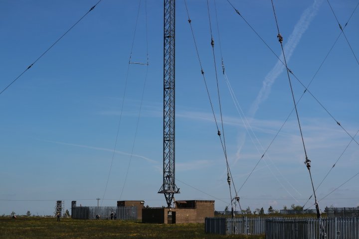
| High-powered transmitting stations employing wire antenna will eventually require these antenna replacing and to do this requires all services turned off for a several hours over a week. The event can be impressive to see when it happens as teams of staff from different backgrounds arrive from all over the country to carryout all types of work from servicing the transmitters to repairing / replacing parts of the structures themselves. During June 2015 this event took place at Moorside Edge. Interestingly no temporary transmitter was used to keep the services on air which is curious as Arqiva have access to a temporary transmitter which was intended for such events as antenna replacement at a main MF site such as Moorside Edge. Unfortunately I only had limited time to visit the site and take a few pictures, but still managed to catch a important stage of the work in progress. |
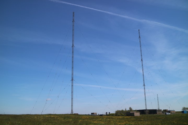
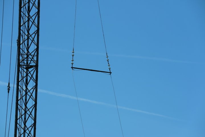
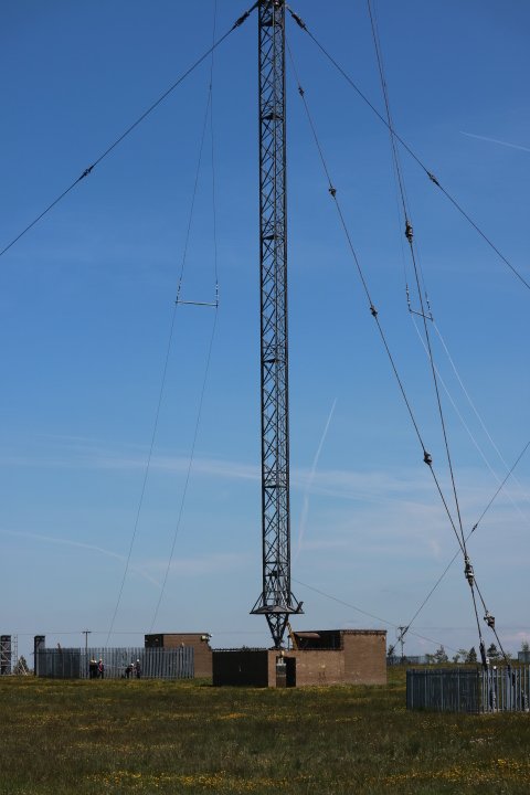
| Two sets of wire antenna are suspended from each mast. The wire antenna are used for the services on 1089 KHz and 1215 KHz. |
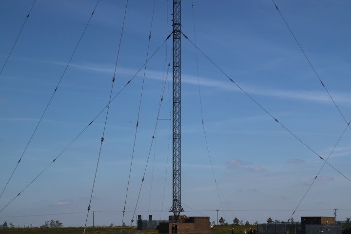
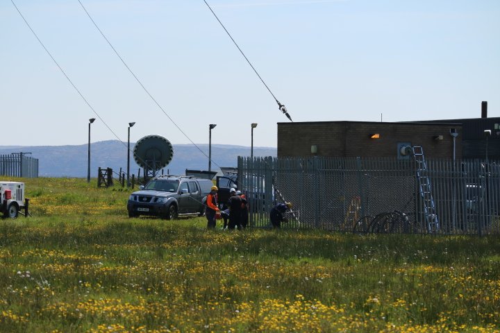
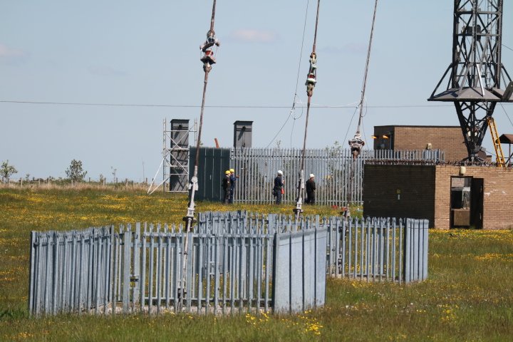
| At the time these pictures were taken the wire antenna had already been removed from the north western mast and the new antenna was in the process of being assembled. |
| The antenna is assembled at ground level and then pulled up via a pulley at the top of the mast. The antenna is pulled up using mobile diesel winches at ground level with a wire running to the top of the mast and then down the near full length of the mast (Inside) to another pulley a few feet above the ground and then to the winch. |
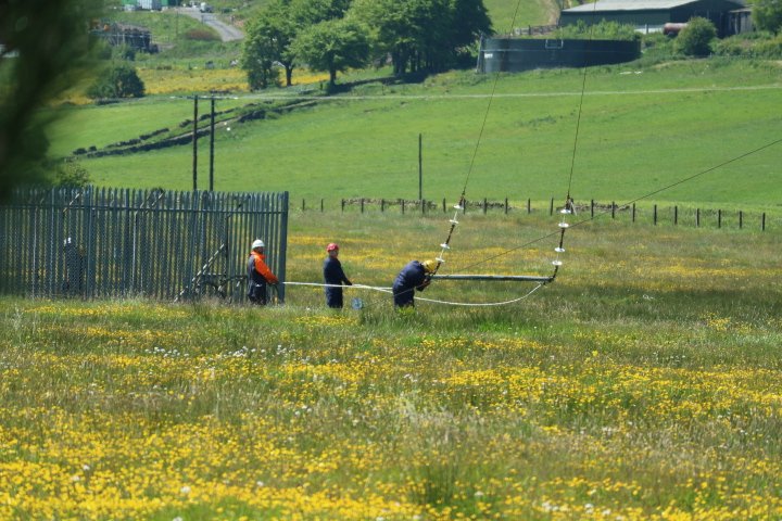
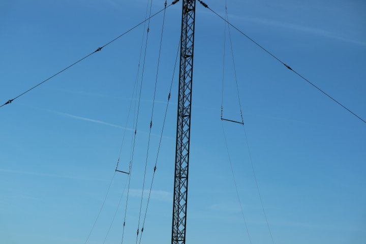
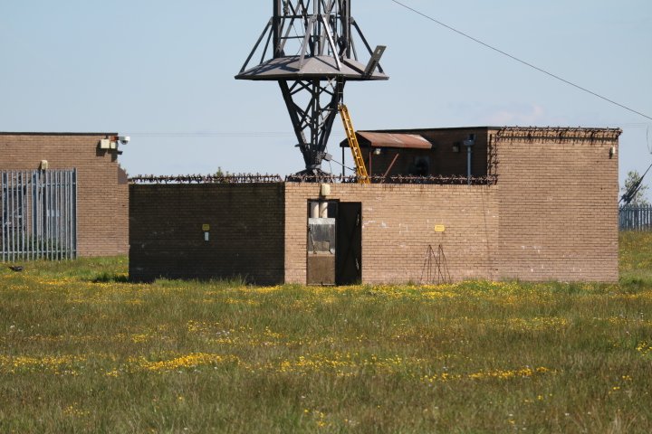
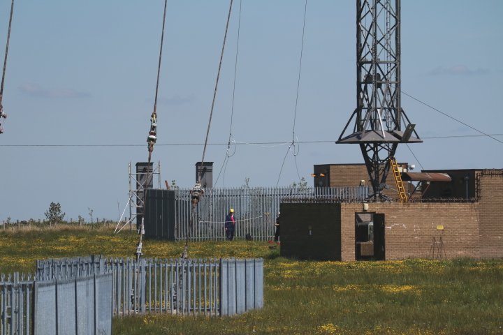
| The antenna is made up of three sections. The first section is purely for support and is attached to the mast and the other end is attached to a triangular splitting/spacing section, again for support. At the bottom of the triangular section are some insulators and then a spacer with the top two wire section of the antenna. |
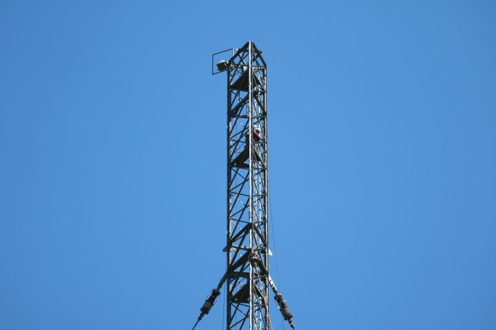
| Triangular section and insulator section now assembled and on it’s way up to the top. Now the assembling of the two wire to four wire section begins with the support section. |
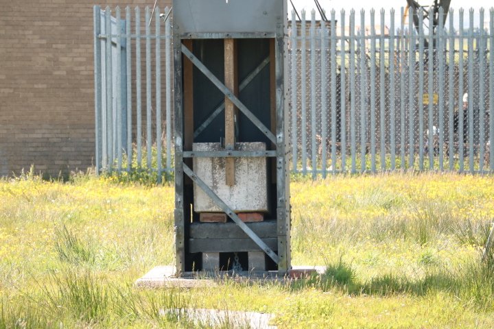
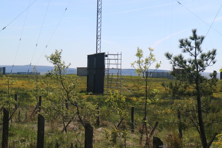
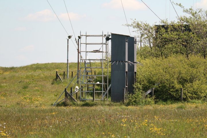
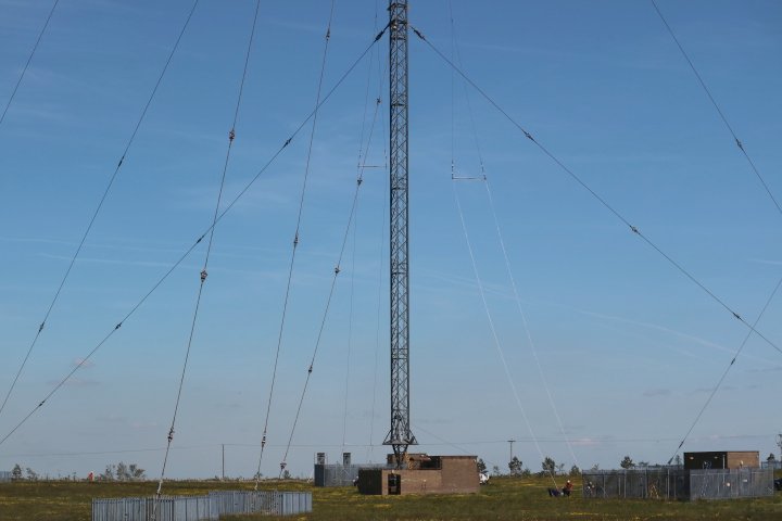
| Concrete weights tension the antenna. When the antenna is full assembled the weights from memory are approximately 1/3 of the way up the box and move slightly with movement of the antenna and mast. |
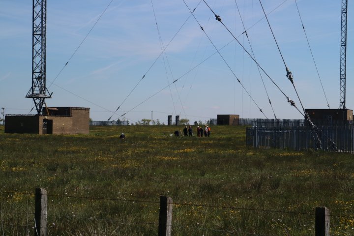
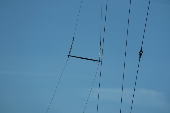
| Assembling of the two to four wire section of the antenna with the support wires which descends down to the concrete weights was possibly the most time consuming stage of assembling the new antenna. |
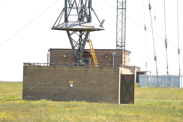
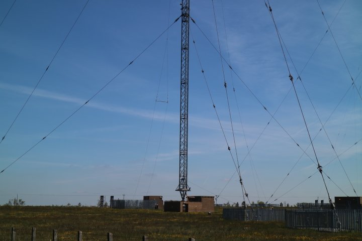
| Can just see the concrete block and base insulators at the base of the mast. |
| The Watchman. |

| Two to four wire section is nearly ready. |
| |
Back to TX Gallery index | TX main index
|