 |
UK Broadcast Transmission |
|
|||||||||||
THE TRANSMISSION GALLERY
HOLME MOSS
| Photos by Alan Drury | Page last updated: 2021-10-16 |
| Alan Drury worked at Holme Moss and Daventry during the 1980s, and has provided some detail of his memories of the era. See link at the bottom of this page. |

| Old VHF FM Hall Left to right: Program Input Equipment (PIE) and drive bays for Radio 2, 3 and 4. The two right hand cabinets are the PCM digital link decoders for the incoming programmes. Two BR1162s on the desk |
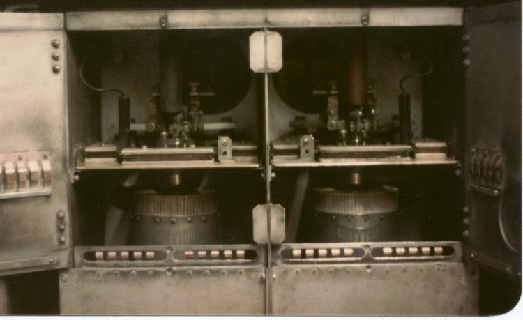
| Old VHF FM Hall Marconi transmitter cabinet open showing two BR1162s in VHF FM final amplifier |
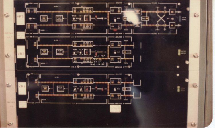
| Old VHF FM Hall Control and indication panel showing all three services |
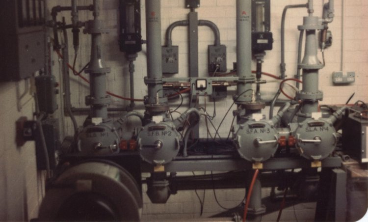
| Old VHF FM Hall Aerial feeder switching, water cooled test loads (note thermometers for power measurement and flow meters on back wall) and feeders to aerials (vertical) |
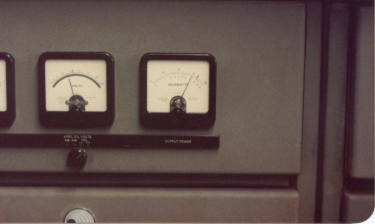
| Old VHF FM Hall ‘A’ side VHF FM transmitter output stage, output power meter showing 10Kw |

| Old VHF FM Hall ‘A’ side, Radio 2, 3 and 4 VHF FM transmitters. The ‘B’ side was opposite to your right. The feeder switches (separate photo) were through the door |
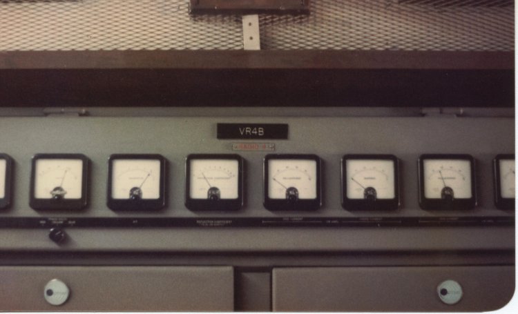
| Old VHF FM Hall General view of VR4B (VHF Radio 4, ‘B’ side) transmitter metering |
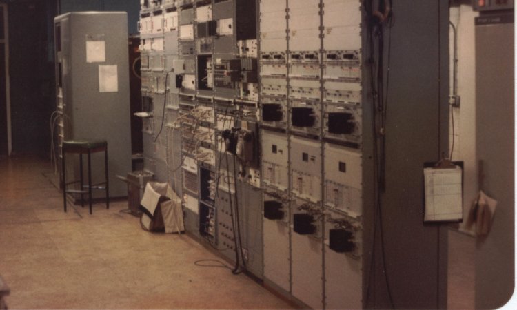
| Local Radio Hall Foreground: Three local radio drive bays, you can see the edge of one of the local radio transmitters to their right. Behind those bays is local radio PIE and behind those is the MIC control equipment. In the background is the standards converter that drove the old 405-line TV transmitter |
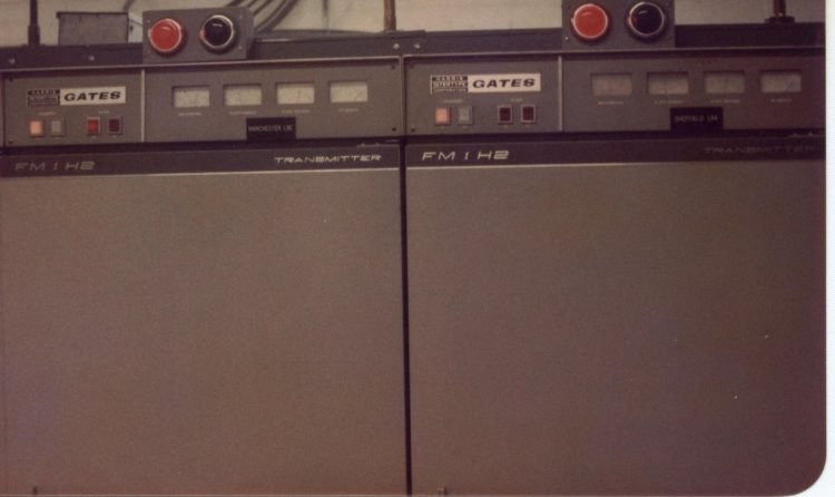
| VHF FM Local Radio Two Gates 1Kw FM transmitters for local radio |
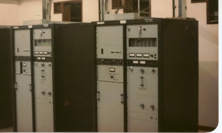
| New VHF FM Hall New Pye transmitters replacing the old Marconi kit. This is the ‘A’ side of one service, there was a ‘B’ side out of shot to the left. The outputs of all the units for all the services were combined into a single pair of output feeders in the combiner hall |
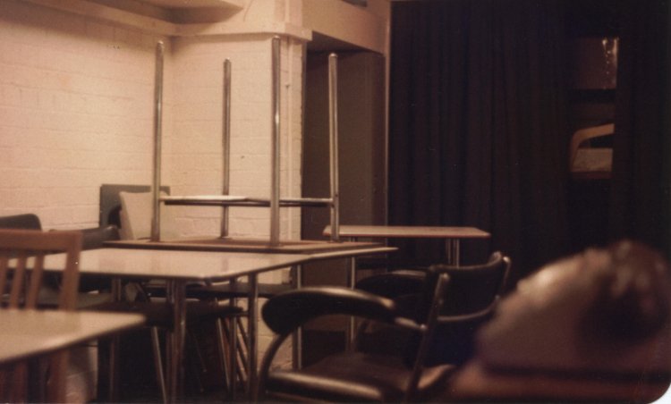
| Basement “Protected accommodation†eating and living area, sleeping area with bunks behind curtain |
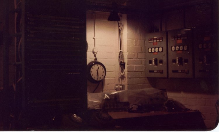
| Basement “Protected Accommodation†operating desk showing generator control panels, audio patchbay and mixer |
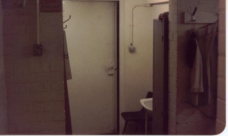
| Basement “Protected Accommodation†washroom and toilet facilities. Operating desk was out of shot to the right and dining/sleeping area behind you |
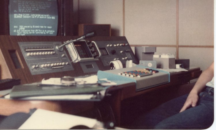
| Monitoring and Information Centre (MIC) Control desk. Left panel: internal intercoms and 2-way radio control panel (for contacting mobile teams). Centre: clock and scope for monitoring video/audio waveform of whatever was on monitor (Holme Moss also monitored the TV output from Emley Moor which ran unattended). Keyboard: for control of the MIC systems and submitting status reports. Right panel: Radio tuner and source selection for speakers. Far right: Dialling cards for the TMIM monitoring units at remote unmanned relay stations. TV display in shot shows the MIC working screen |
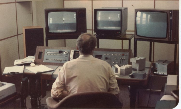
| Monitoring and Information Centre (MIC) General view showing video monitors and really good speakers. Anything could be selected for monitoring. To operators left: phone handsets and printer which kept a constant audit log of everything happening in the Holme Moss area of responsibility. Engineers did stints on the MIC by rota. The operator also had to report the weather observations to Bawtry twice a day |
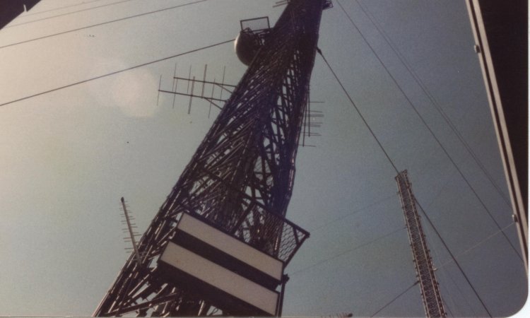
| Outside Old mast with new mast under construction to the right. While I was on staff Fred Dibnah climbed it and did a live broadcast from the top, famously commenting “It’s bloody cold up ‘ere!†live on air. |
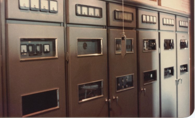
| Band I TV Hall The old Band I TV transmitter. I was the one who turned it off for the last and final time, a bittersweet moment. ---------------------------------------------------- Below onwards: Photos of the damage caused by the ice fall at Holme Moss in early 1986. They were taken in a rush in a moment of opportunity and as far as I know are the only ones showing this much detail. I was on staff at the time. When the mast iced up they told us all to stay home and phone in each week, leaving just a few key people onsite. After it fell we all got called in to help which is when I grabbed the pictures. |
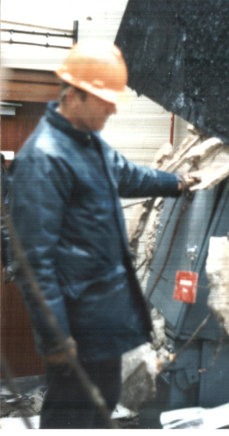
| Ice Fall Engineer examining smashed HV switchgear in the HV switchroom. Transmissions were unaffected as the Moss, like all major transmitting stations, had dual HV supplies coming in from two separate directions into two separate HV switchrooms plus its own standby generators. |

| Ice Fall Engineer examining transformer in the LV switchroom. Taken from outside the external access door |
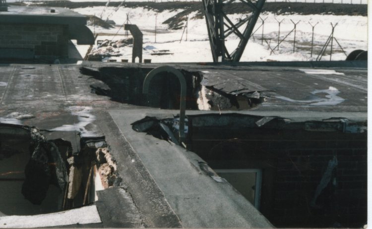
| Ice Fall View of holes in roof. Also a good view of the bottom of the old mast, this came to a point and sat on a huge greased ball, the rigging was what kept it upright |
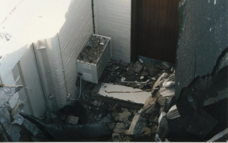
| Ice Fall View from the roof looking down into the room where the transformer was, showing the external door which that photo was taken from |
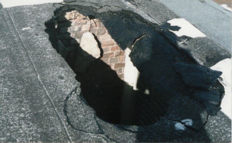
| Close view of one of the holes in the roof |
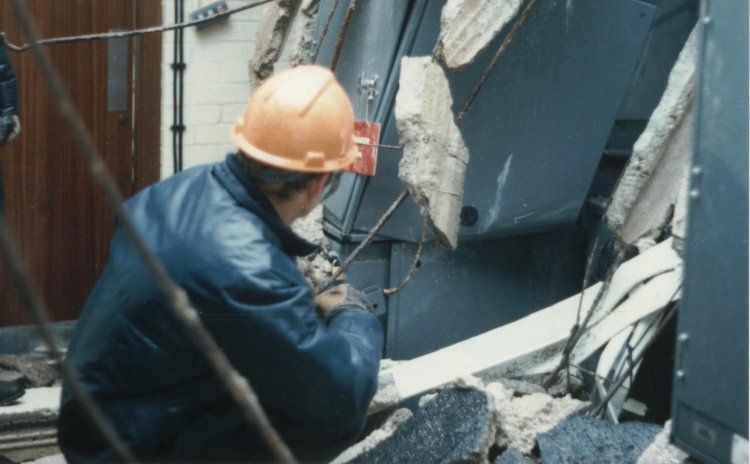
| Another view of engineer examining smashed HV switchgear in the HV switchroom. Note the metal rebar in the roof concrete and the light switch hanging off the wall |
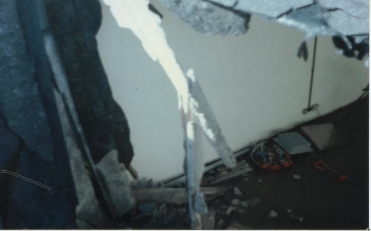
| View down into one of the rooms through hole in roof |
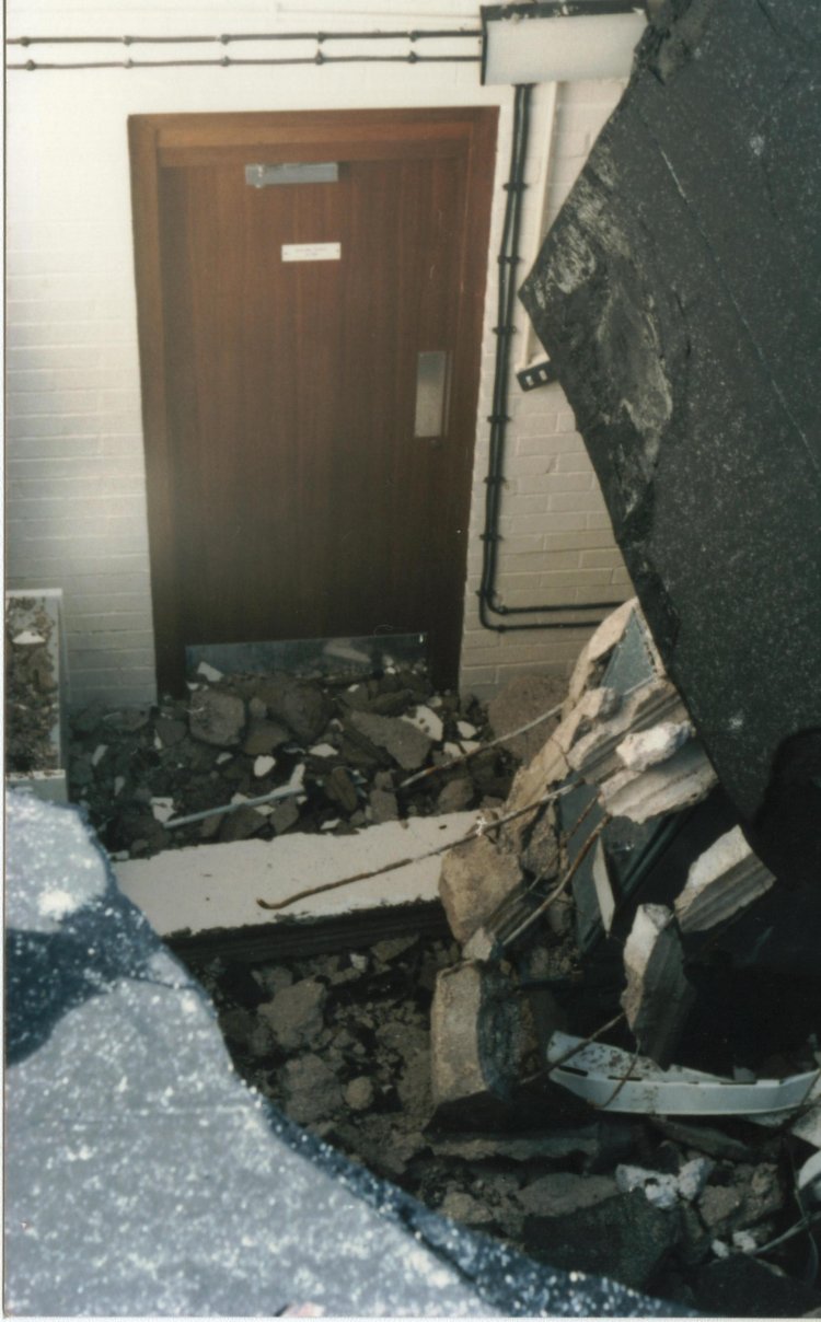
| View down into the wrecked HV switchroom |
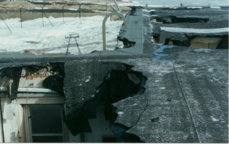
| General view of damage to roof |
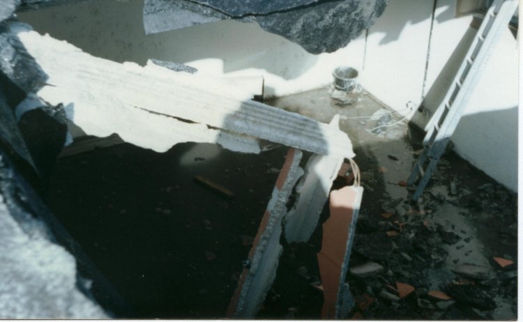
| View down from the roof into one of the rooms |
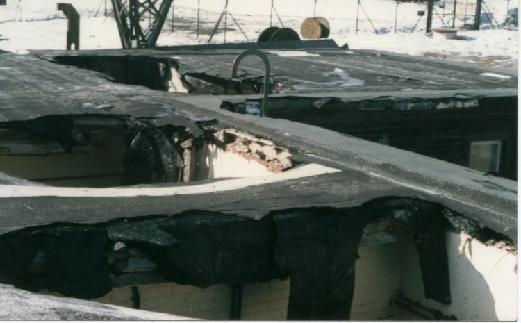
| Wide view of damage to roof |
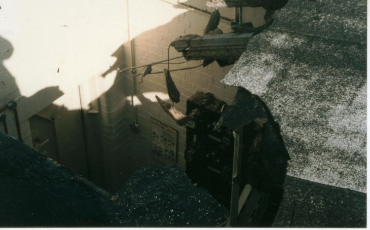
| Close up of edge of one of the holes |
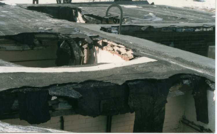
| Wide view of damage to roof |
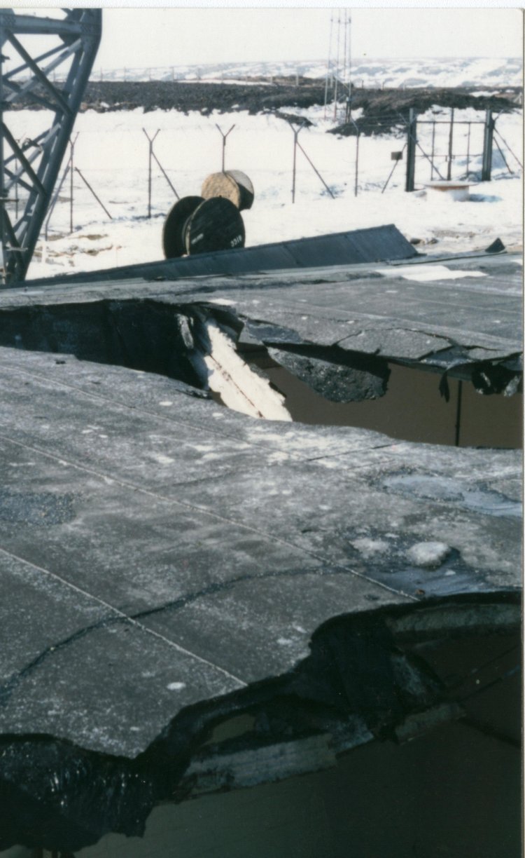
| Another view of damaged roof and bottom of the old mast |
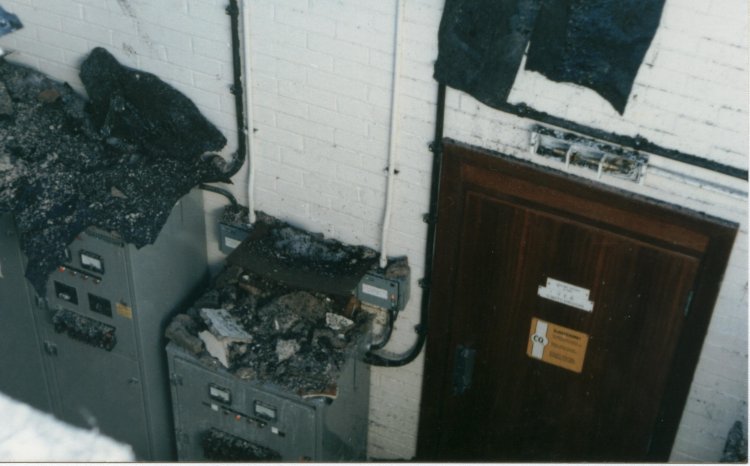
| View from roof down through hole into HV battery room. The door leads into the HV switchroom. The wrecked light above it showed the status for the fire suppression system |

| Another view of damaged roof and bottom of the old mast |
Alan Drury's Memories of Life as a BBC Tx Engineer
| |
Back to TX Gallery index | TX main index
|