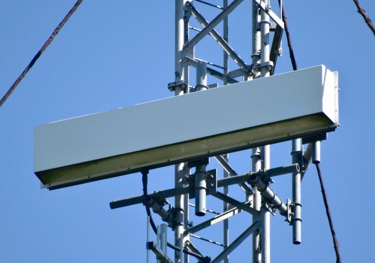
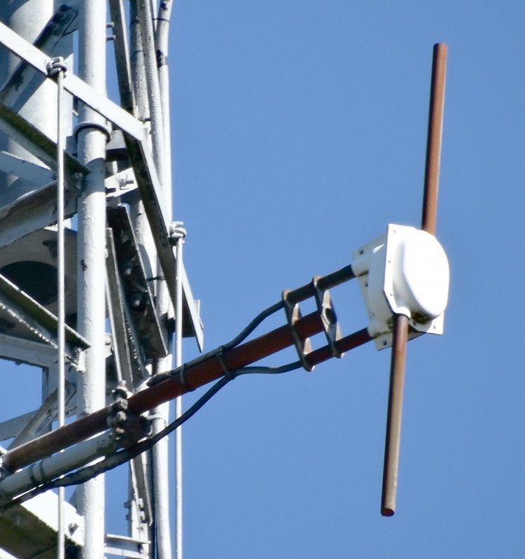
FM radio transmit. This appears to be a Marconi R8000 dipole which were commonly used from the mid 1980s onwards. Unfortunately no specifications can be found for this aerial but we assume that the junction box does not contain a transformer balun. Note that there are two cables entering the dipole, one each through a pair of grounded metal tubes.
John Martin writes: The lower coax feeds RF power to the dipole, with screen to one leg and inner conductor to the other. As coax is electrically unbalanced and a dipole is balanced, some form of 1:1 balun is required. It seems that the upper coax is a short-circuit terminated 3/4L stub which acts just like a 1/4L stub. It is also connected across the dipole feed points but the opposite way around from the feeder. This forms a choke balun. As all aerial elements need to be DC earthed for lightning protection, it seems that this is achieved by the two metal tubes which were are also connected to the dipole feed points. They appear to be 1/4L long and thus appear as an open-circuit to RF and have no effect, but as a short-circuit to ground at DC and provide mechanical mounting for the dipole. Both the coax stub and the mounting tubes would further limit the bandwidth of the dipole.
Dave Thickett, who installed a few of these during his time at the BBC in the 80s and 90s, adds: The return loss of these dipoles was around 20dB over a bandwidth of 10MHz when the dipole was spaced at least a quarter wave or more away from the backscreen. BBC R&D used to design the antenna system back in those days, they would specify the spacing of the dipole from the backscreen and the width of the backscreen needed to give the HRP that they had used in their service planning/coverage plan (usually modelled in NEC). Sometimes the dipoles were specified to be less than L/4 away from the screen and the dipole would need matching. We did this by calculating the position in the transmission line feeding the dipole where a small capacitance could be inserted to improve the return loss. At this point, we would cut the transmission line, insert a 'tee' piece and put a short length of open circuit line in (a capacitance as long as it was less than L/4), which we would cut down until the match was optimised in the part of the band we needed. The problems came when we started to add R1 and R4 to the low power relays in Wales and Scotland and the 10MHz bandwidth of the Marconi dipole was no longer adequate. I had moved on into the DAB/DTT team by then but we had a big stock of these dipoles to use up and the other engineers had to come up with some crazy stub matching/quadrature ideas to get them to work. |

