 |
UK Broadcast Transmission |
|
|||||||||||
THE TRANSMISSION GALLERY
CRYSTAL PALACE
| Photos by John Rhodes | Page last updated: 2024-04-07 |
| In 1969 all three UHF channels at Crystal Palace were equipped with new Marconi 2x40kW parallel pair transmitters for the 1000kW erp aerial. Neither of the other two 1000kW sites at Sutton Coldfield and Sandy Heath required this amount of transmitter power as they both used an aerial system with higher gain. The majority of main UHF sites were designed to use a common transmitting aerial with pairs of channels being combined in a two channel combining unit to provide two feeds into a four channel combining unit, but at 10 sites there were separate BBC and IBA aerials. Crystal Palace was one of these 10 sites. The higher transmitter power at Crystal Palace was required because the BBC opted for an aerial system with lower intrinsic gain. This was probably because they had been concerned about the vertical radiation pattern causing problems with close-in reception. Doubtless the much higher power and voltage handling of one aerial and its four channel combining unit would have come into play, the result of which was that two separate transmitting aerials were installed, without the need for a four channel combining unit. One aerial was for the BBC channels and the other for ITV and the unallocated fourth channel. Each aerial of course was in two halves as at all main stations, each half being fed by its own main feeder. BBC2 transmissions from 1964 used a parallel pair of early generation Marconi 25kw transmitters which were almost entirely valved. They used water cooled Eimac klystrons with high level air cooled VSB filtering. The outdated 2x25kw set was moved to BBC1 Divis to be alongside a similar Marconi 25kw pair already in use for BBC2. |

| This was the IBA building in the 1970s with its poor architectural join to the BBC building. In 1969 this building was unique among all high power UHF stations in that it was built large enough to accommodate a transmitter for the unallocated fourth channel. On the ground floor at the front were high voltage transformers, AVRs, MV switchboard and Post Office lines room etc. Upstairs were building ventilation blowers and heat exchangers. Behind this front part of the building were two underground transmitter halls with fire escape stretching about 25m further back towards the tower base. Being underground, these transmitter halls are not visible on any 'satellite' view, though the fire escape can be seen. |
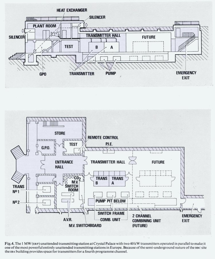
| Drawing from IBA Technical Review 4 |
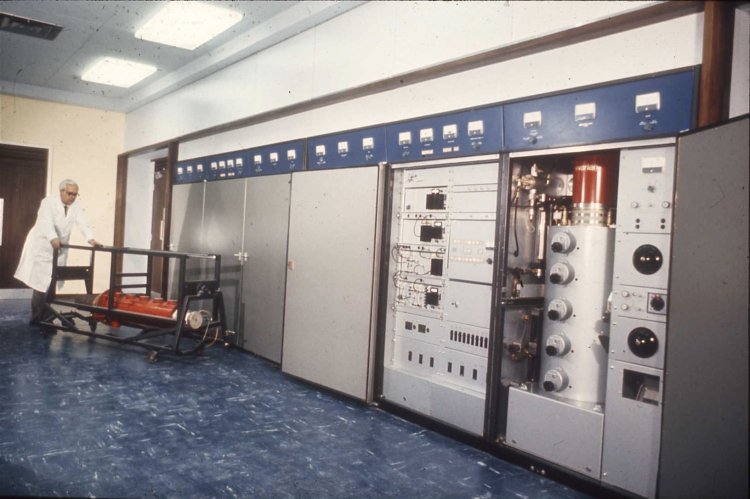
| Marconi B7318 2x40kw transmitter showing one of its four 5 cavity klystrons sitting in a magnet assembly. |
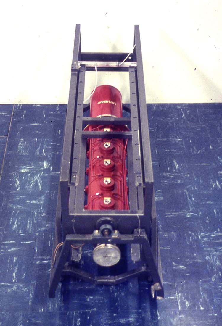
| Varian 40kw klystron. The ITA specified the use of integral cavity 50db gain Varian klystrons while the BBC used external cavity ones made by the English Electric Valve Company aka EEV now E2V. The advantage of 50dB gain klystrons was that they only required ½ watt of drive power, which was readily available from semiconductors of the 1967 era. Notwithstanding the significant advantages of very high gain and power handling, klystrons were very inefficient. The normal peak sync efficiency was only about 30%, compounded by their operational equivalence to Class A. There was an instability during initial testing of the Varian klystron, said at the time to be multipaction. Varian's answer was to increase the beam voltage to 23kv (beam power 156kw) from the 21.5kv (beam power 132kw) used by EEV klystrons, worsening the efficiency quite considerably. Cooling was done with water through the maze of small pipes along the body and then up to the collector where it boiled. The steam was condensed in heat exchangers upstairs. The klystron shown here was for low band use (channel 23 at Crystal Palace) but high band ones were very much smaller. Back in 1969, these klystrons cost over £5k each and global warming was not regarded as an issue. |
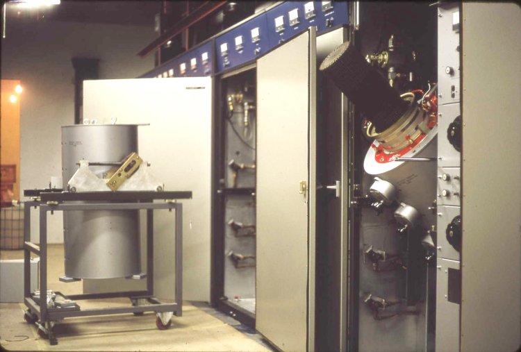
| Taken during the installation in 1969, this photo shows a magnet assembly ready for pushing into place, with a vision klystron deliberately partially tilted showing the collector without its boiler. The klystron was inserted/replaced from a trolley butted up against the magnet assembly when horizontal. This was in contrast with external cavity klystrons used elsewhere, which had to be hoisted vertically and dressed with their cavities before being lowered into a magnet assembly. |
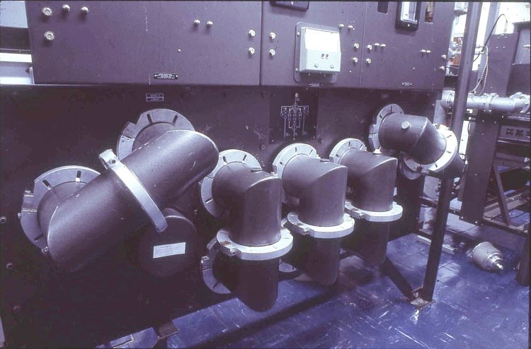
| The switching frame had large 'U' links which permitted selection of water cooled test loads and the bypassing of the transmitter combining diplexer and aerial splitter. The link in the centre connecting the diplexer to the splitter carried the combined power of 80kw peak sync and 16kw FM sound. If the truth be known, this power exceeded the 1000kw erp permitted limit. |
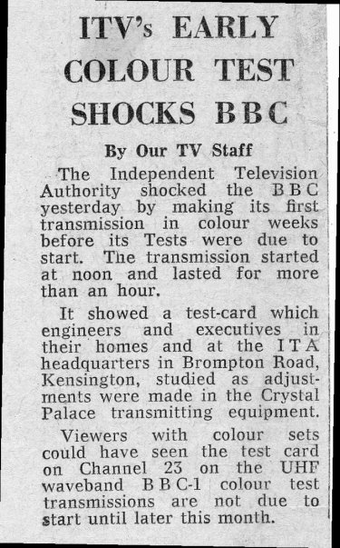
| On 5th September 1969, the front page of the Daily Telegraph carried this piece, clearly primed by the ITA information service. The transmission was at half power and the test card showing no identification came from a slide scanner at the Croydon site. |
Engineering for Colour (ITA 1970)
The Crystal Palace UHF aerial (BBC RD 1968)
IBA Technical Review index
| |
Back to TX Gallery index | TX main index
|