 |
UK Broadcast Transmission |
|
|||||||||||
THE TRANSMISSION GALLERY
SUTTON COLDFIELD
| Photos by TCPD | Page last updated: 2024-12-31 |
| When Digital Terrestrial Television (DTT) was first introduced it had to share sites antennas and spectrum with existing analogue services and initially used low power, and in some cases directional antennas, in order to avoid any significant interference to the analogue TV. The information here records how this was implemented at Sutton Coldfield. None of this equipment is still in operation. It was all replaced at the digital switchover. |
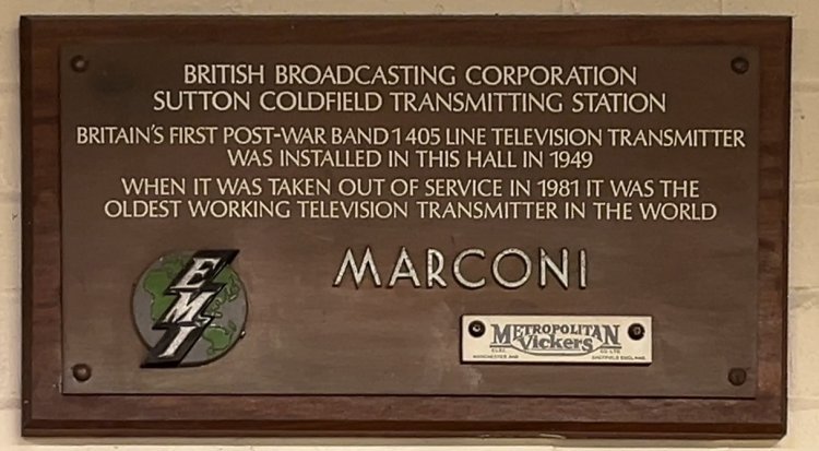
| This plaque is in the hall which now houses the VHF/FM amplifiers. I take it the badges were recovered from the scrapped transmitters. A gathering of former and current staff was held on 17 December 2024 to mark the 75th anniversary of the opening of the station. |
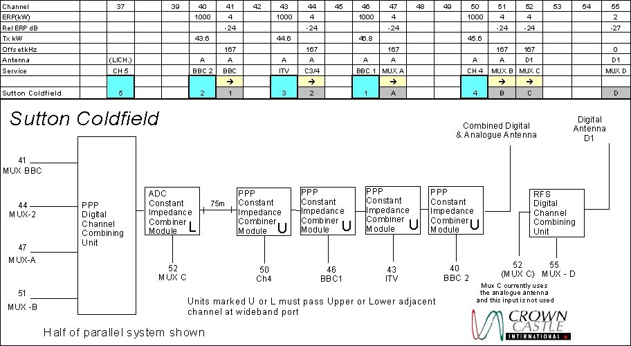
| This diagram summarises the station configuration and channels for the addition of the DTT services. ADC refers to supplier Alan Dick and Co. PPP is Passive Power Products (USA) and RFS is Radio Frequency Systems (Australia) |
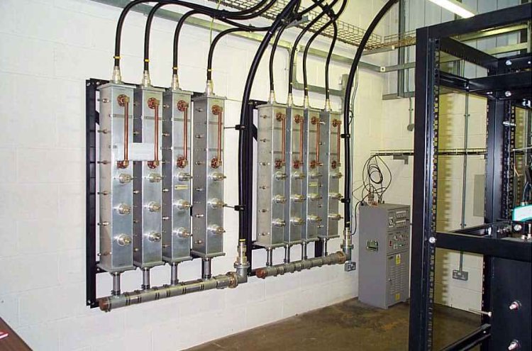
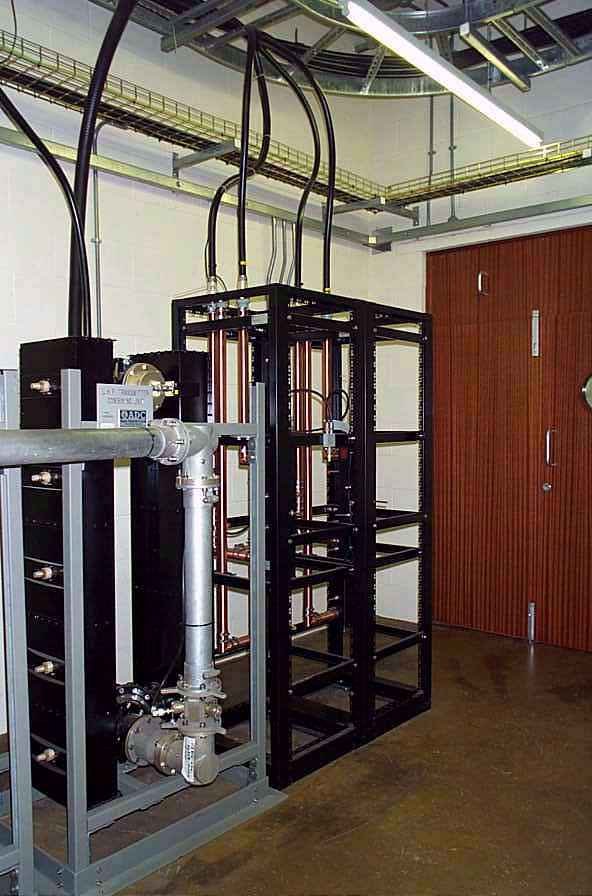
| Starting in the new DTT building, the four channel combiner is of the "manifold" type where the four 5 cavity bandpass filters feed into the coaxial feeder at the bottom. By magic of the correct spacing of the connections everything emerges at the output. Excitingly, the second of these unit only arrived on site from the USA on the day before the services were due on air. |
| The outputs of the four channel unit then go to the Channel 52 combiner which is a pair of constant impedance networks using 5 cavity waveguide filters and from there to the 75m long 2 1/4" cross-site feeders to the analogue building. On the right are the RFS 2 channel combiners for 52/55. A late change in the customers plan was to switch channel 52 from the DTT to the analogue antenna; hence these were only retained as providing some reserve facility. |
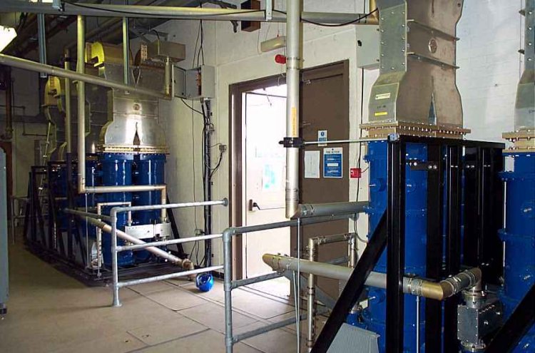
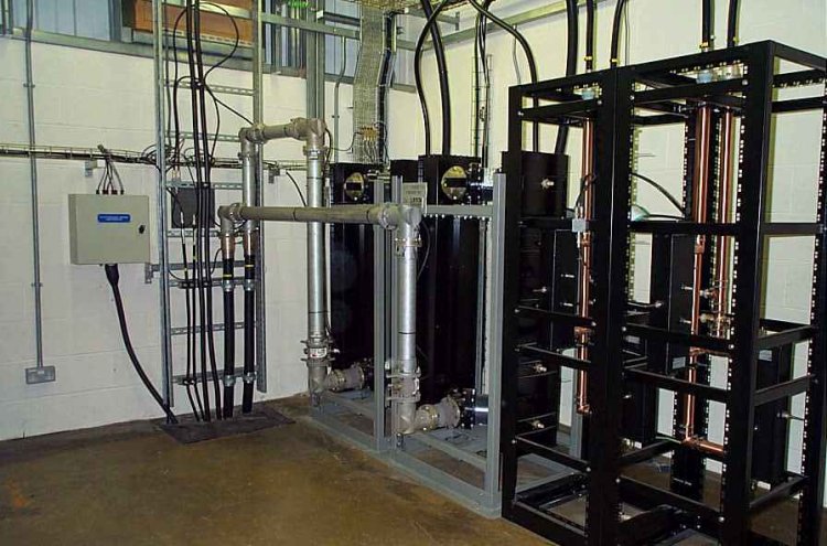
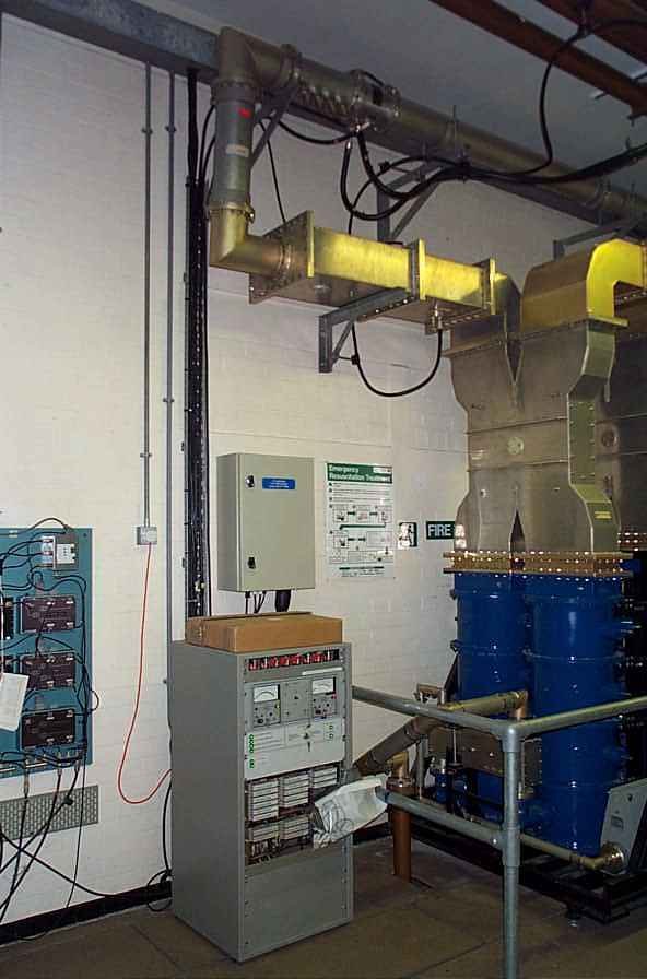
| Here in the original BBC UHF building is one of the most spectacular bits of kit we installed for DTT. Each analogue channel is filtered and combined in a constant impedance network comprising a 3dB coupler with coaxial ports at the input, two 4 cavity dual mode waveguide filters and a waveguide 3dB coupler at the output. The dual mode filter means that each cavity has two independent resonances so that the response is equivalent to an eight cavity filter. (But half the size!) The filters are made from silver plated invar to maintain the performance over the operating temperature range. We can see one of the IBA channels come into this building under the floor on either side of the door and go on 3 1/8" rigid feeder to the second module input. |
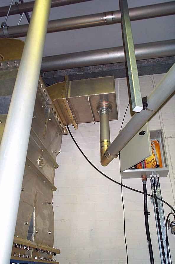
| The 5 combined DTT channels arrive from the DTT building and enter the channel combiner through the transition from 3 1/8" rigid feeder to 15 inch waveguide. |
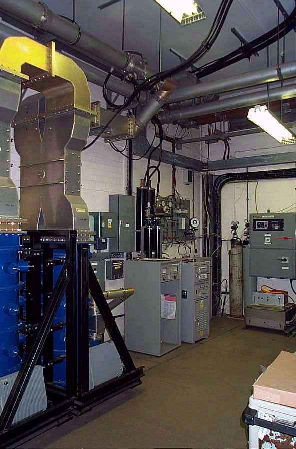
| At the output of the combiner there is a transition from waveguide to 6 1/8" feeder followed by a matching section and a precision directional coupler which drives the antenna forward and reverse power meters. |
| Unlike the right angle configuration of the input waveguide transitions, the output coax is inline with the waveguide. Hence it is not immediately obvious if the transition is fitted upside down. Unfortunately the installers did just that, resulting in some head scratching when it was not possible to match up the phase of the two chains of equipment. |
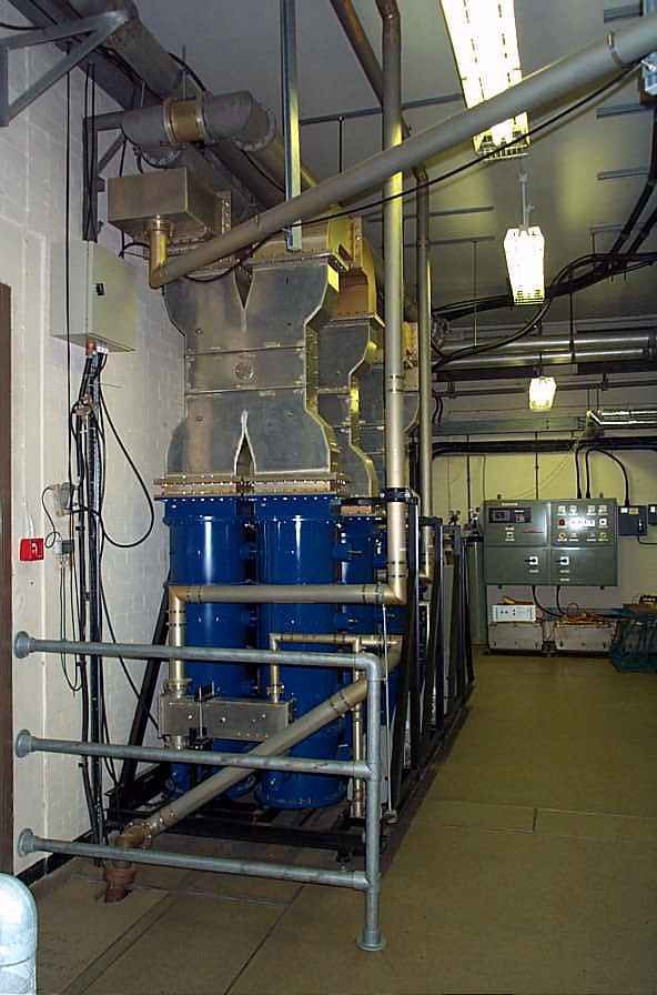
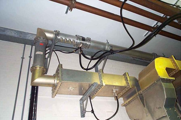
| Feeders to the mast exit at this end of the room. There can be seen the feeder pressurisation equipment and a channel combiner for the local radio FM services. (BBC west Midlands and an ILR service) The UHF main feeders were pressurised to 2 bar in order to increase the power and voltage handling ability. |
| |
Back to TX Gallery index | TX main index
|