 |
UK Broadcast Transmission |
|
|||||||||||
THE TRANSMISSION GALLERY
WINTER HILL
| Photos by John Rhodes | Page last updated: 2024-04-22 |
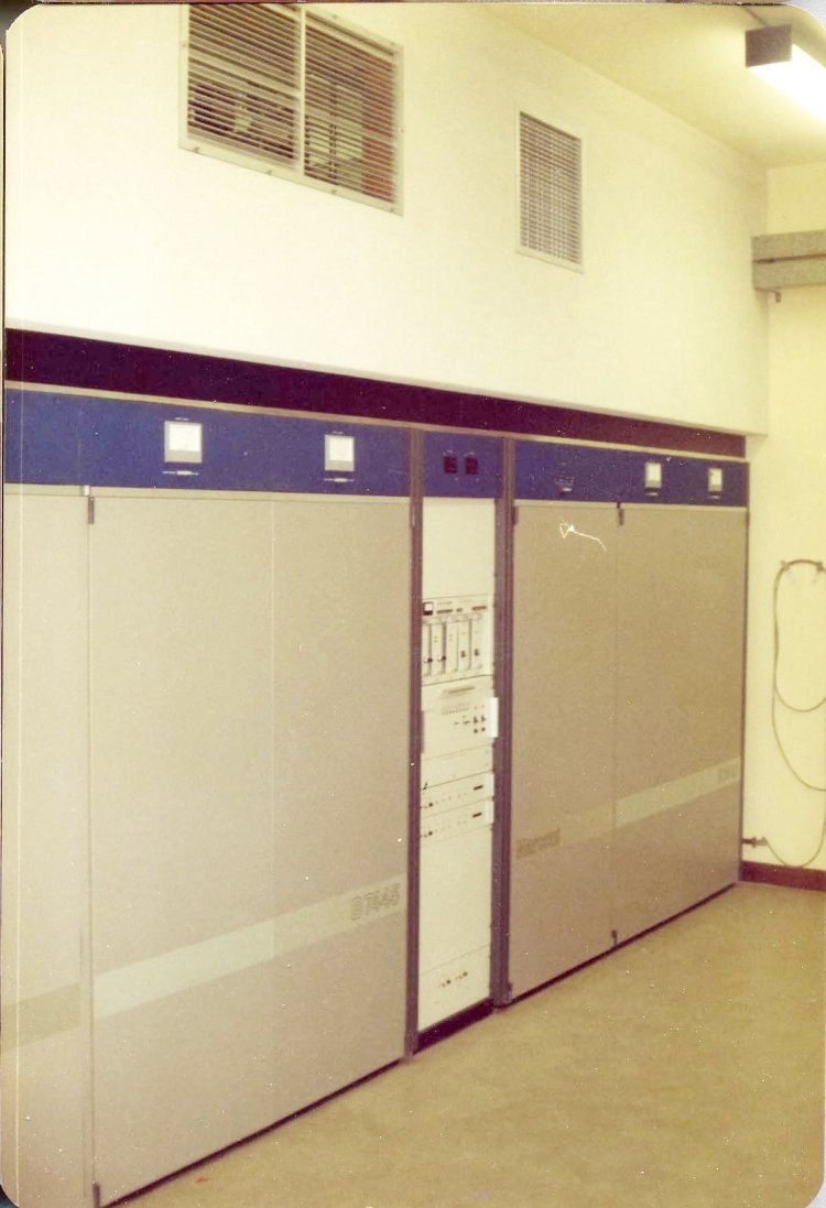
| Winter Hill Channel Four. Marconi 2x10kw transmitters in 1981. |

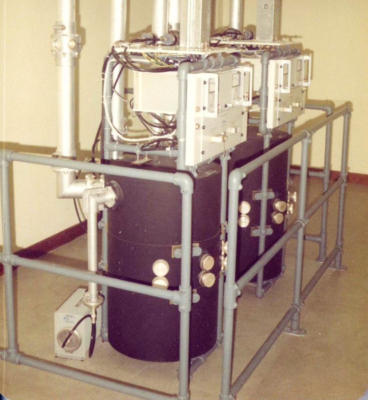
| The Marconi 2x10kw transmitters for Channel Four used Valvo vapour cooled collector up external cavity klystrons. Valvo was a valve manufacturing arm of the Philips electronics company. The photo shows two klystron assemblies for separate sound and vision amplification. The Valvo klystron was an improvement over earlier klystrons as it had better beam focussing. In earlier systems the magnet coils surrounded the whole klystron and cavity assemblies for both integral and external cavity klystrons. The Valvo coils were situated between the cavities and were therefore very much closer to the klystron giving better control of the beam focussing. |
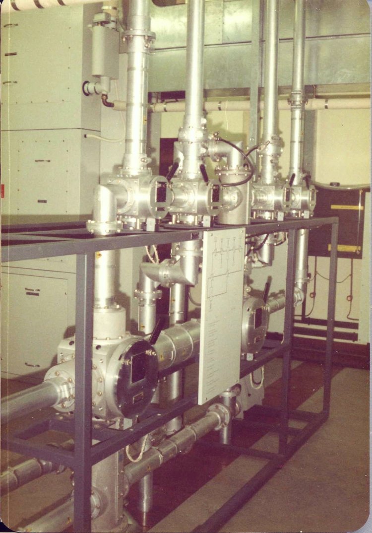
| Pair of Marconi Rotamode sound/vision combining units for the two Channel Four transmitters. This rotamode system was also used for the two channel (ITV and Channel Four) combining units. In addition it was used for out of band filtering on channel 21 sites (470MHz) owing to the stringent specification protecting the 460MHz communications band. The Rotamode sound/vision combining unit may be viewed as a balanced directional coupler within a cavity resonator which is tuned to the sound frequency. Vision passes into its coupler and out again without crossing over to the sound coupler (being outside the tune of the cavity). Meanwhile the sound enters its coupler and is passed across to the vision coupler (being enabled by the cavity tuning) where it joins the vision signal. A sound/vision combining unit contained a second resonant cavity to reject out of band image subcarrier radiation ie fv-4.43MHz. The output port of the sound coupler was connected to an air-cooled load, as shown in the photo, to terminate vision sidebands close to sound and also any rejected image subcarrier energy. |
| Channel Four aerial switching frame The switching frame enabled individual or both transmitters to be connected to test loads and also to bypass the transmitter diplexer and aerial splitter. Unlike earlier systems which used 'U' links, this used manually operated coaxial switches. |
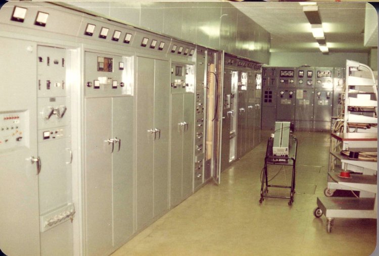
| This is a 1981 photo of the ITV transmitter installed in 1969. It was a Pye TVT 2x10kw using English Electric klystrons. Nearest on the left is the HT cabinet and control unit. Next along (with low height doors) is a klystron cabinet followed by the sound/vision combining unit cabinet and then another klystron. Beyond this is the low power driver transmitter (approx 2 watts) next to the phasing and oscillator switching cabinet (door ajar). Phasing was done by means of motorised trombones. |
| |
Back to TX Gallery index | TX main index
|