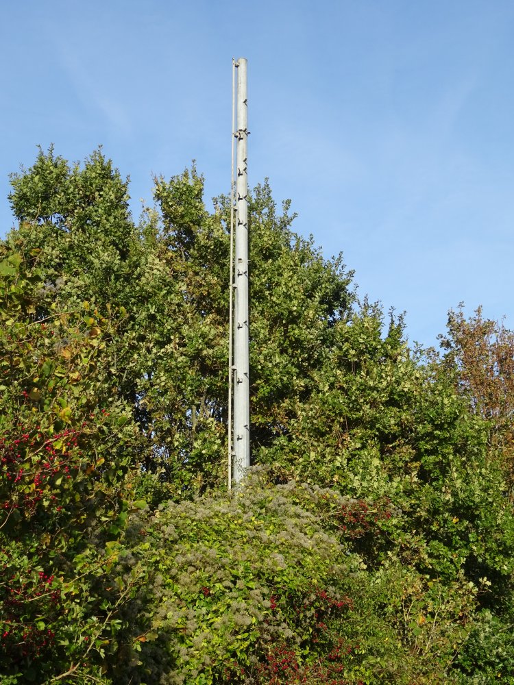
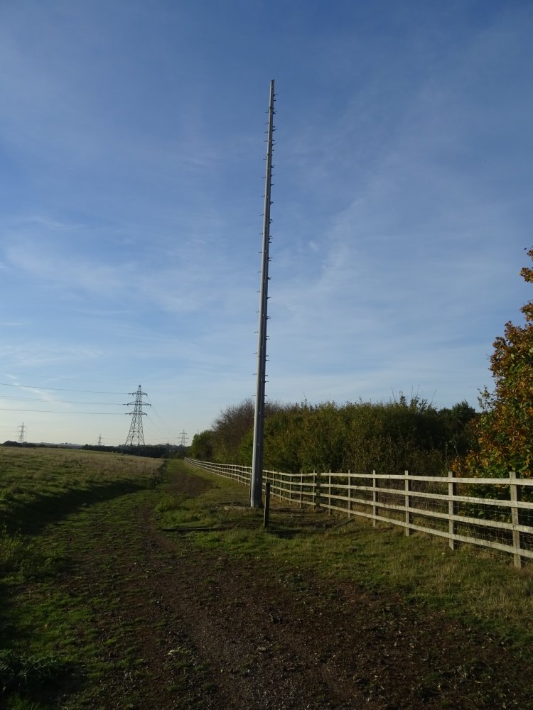
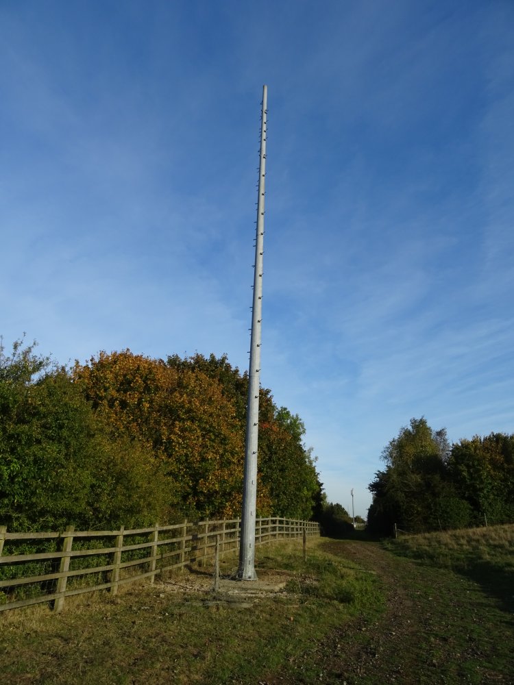
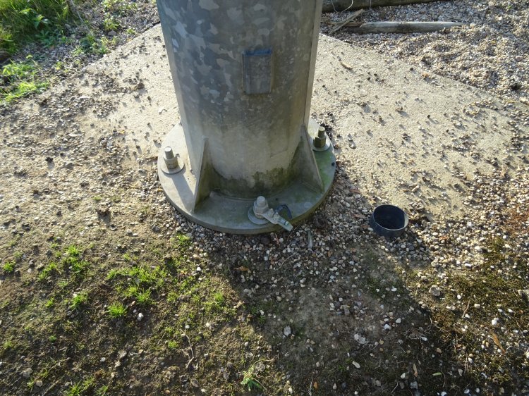
Sellinge was the first in a chain of three relay transmitters for Channel Tunnel Radio. A long term RSL which operated from 1995 to 2000. The base transmitter was at Stone Farm and that gallery page has more about the history of this radio station. The two downstream relays were at Evegate then Willesborough.
The RSL licensing restrictions meant that relay transmitters were required for the Channel Travel Radio service. These relay transmitters needed to be close to the motorway (within 100m in fact) and spaced every 3-6 km depending on the terrain. Each relay used a pair of pole masts, one for the receive antenna and one for the directional transmit spaced 140m to 270m apart. The spacing allowed enough isolation between the receive and transmit side since they used the same frequency. The antennas were slant polarised with the polarisation reversing between receive and transmit to further increase isolation. According to planning applications the receive poles are 12m high and transmit 17m.
The technology used by the relay transmitters was quite simple. They were antenna>filter>amplifier>filter>antenna. In theory any transmission within the bandwidth of the filters (+/-1MHz) could have been passed through the system. NTL chose to purchase an ‘off the shelf’ solution for the relays from French company Velec. The company still exists and claims one of its main achievements was inventing a sausage counting machine in 1991. An alternative had been offered by UK company SBS which would have mixed down the receive signal to 10.7MHz where the filtering and limiting would be done before mixing back up to the transmission frequency. Filtering at 10.7MHz is easy, cheap and very effective. This system was never developed.
The receive pole mast had a small cabinet mounted on the pole which housed a large bandpass filter, attenuator/splitter, pair of variable gain pre-amplifiers and combiner. This required an AC power feed, RF cable and AGC voltage from the main cabin at the base of the transmission pole. A small greenhouse style heater was fitted in the base of the receive cabinet.
The transmitter/amplifier system was housed in a small cabin approximately 2m square at the base of the transmit pole. The cabin contained a splitter, pair of amplifiers, level detector (for the AGC), combiner and filter. The transmit antennas were a pair of log periodic type mounted one above the other.
Only the Willesborough relay site still has the transmit cabin. |


